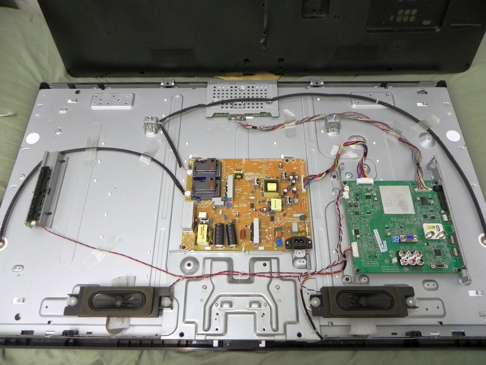
Here is a picture inside the TV without the rear cover. The power supply includes the inverter stage for the backlight panel using only two HV transformers. Such design idea sounds very good because all EEFL tubes are connected in parallel avoiding the use of small transformers/inverters stages for each lamp minimizing in this way electronic issues on the backlight stage.
Compared to former CCLF, the new EEFL shows superior performance and applications. This incredible technology combines low power consumption and enhanced luminescence as compared to similar lighting sources. The most attractive feature of EEFL (External Electrode Fluorescent Lamp) is the absence of electrodes in the discharge tube, which is the main factor limiting lamp life. Electrode burn-out is the main cause of fault in CCFL. Because each CCFL lamp need its own ballast the new EEFL technology is simpler in electronics circuitry reducing in this way the rate of failures. EEFL lamps consist of a completely enclosed glass tube with external metal electrodes at both ends. This design minimizes electrode burn-out and results in a longer lamp life. Because the electrodes in former CCFL technology are in direct contact with the rare gasses, CCFL run warmer than the EEFL which are completely cool. On average, EEFL lamps have a lamp life of over 50,000 hours.
The overall power supply circuitry is pretty well cooled using passive heatsinks with enough space for convection air flow. Also the components are excellent in quality specially the filtering capacitors which guarantees a long durability.
If an electronic IC heats to much this situation can lead to failures on the device. On some circumstances excessive temperatures can lead to a short circuit inside the silicon core leading to damages on external connected devices (video card/HDMI ports, USB storage devices, etc.).
I figured out that three main areas on the circuit layout requires additional cooling. The hottest part was the digital class D audio amplifier (STA381BW) because overheats to much (manufacturer datasheet claims approx 3 watts of heat dissipation !!!) so I put a passive aluminum cooler to cool it down. Because the rear plastic cover touched the cooler I cut one of the corners. Using a smaller one was to weak to cool down the device at safe temperatures.
 |
| The STA381BW class D amplifier |
The digital scaler image MT5366 processor and glue logic ICs are located below a metallic RFI shield acting at the same time as a heatsink. Unfortunately the metal shield in use affects the efficiency on thermal conductivity of heat because is to thin leading to hot spots on the components. To correct such design issue the most convenient is to install a passive cooler. To cool down the MT5366 system on chip platform processor an older 486 mother board heatsink (the black one after changes third picture below) do the job well. The use of a thicker heatsink improves the thermal conductivity (spread of heat) avoiding hot spots on the devices.
On datasheet the TV set claims to use the MT5366 audio and video processor (system on chip platform). It combines front-end video processing functions such as DVB-T/C/S channel decoding, analog video decode and HDMI reception, integrated USB 2.0 controller, motion accurate pixel processing & MPEG-2, H.264, MPEG-4 decoders (DCT discrete cosine transform), color gamut and booster, MPEG artifacts reduction, Ethernet interface support enabling IPTV (Internet TV), VOD (video on demand), ARM core based engine. The LVDS (low voltage differential signaling) bus to T-CON panel board support scaling resolutions including 1366x768 and 1920x1080 formats plus a backlight dimming function (dynamic contrast).
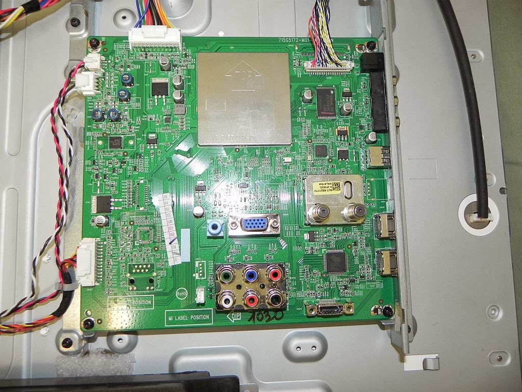 |
| The main board before changes |
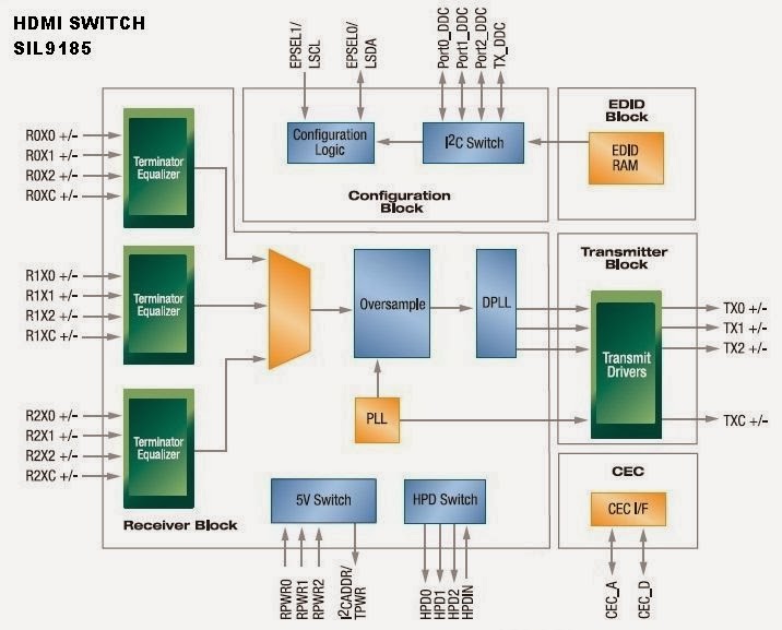 |
| The HDMI switch/inputs selector (SiI9185) |
The last part that requires additional cooling was the HDMI switch inputs selector (SiI9185 device schematic picture above) soldered on the right corner next to the HDMI inputs. Its based on the HDMI 1.3, DDC, HDCP specifications including a CEC (consumer electronics control) single wire bus interface to transmit I/O remote commands through a home network and EDID display identification (plug & play feature stored on serials EEPROMs). Researching datasheets from other versions I figured out that the device in operation consumes approximately 1.5 watts average but such information is not released by manufacturer. The device reach a working temperature of approximately 100 grads Celsius when HDMI inputs are enabled receiving stream data. Watching TV channels (digital DVB or analog cable) the HDMI switch remains cool because is in power down/suspend mode. At glance the HDMI switch overheats only when the inputs are enabled. Without an appropriate heatsink the life endurance of the device is affected because such operating condition can lead to a short circuit on terminals due silicon breakdown !!! . The HDMI switch integrates electrostatic discharge protections on its inputs up to 2kV discarding any possibilities of damages due weak ESD spikes but strong lightning electromagnetic discharges are a big problem without ESD protectors.
In the case of factory cooling all mentioned devices use the "ePad" enhancement, a small metal surface below the IC core case to transfer the silicon heat to PCB board. Despite the idea to reduce manufacturing costs avoiding in this way the use of external heatsinks such cheap PCB cooling solution is not appropriate at all. We verified on all the mentioned devices an excessive heat that unfortunately can lead to operational malfunctions/issues leading to a short durability.
 |
|
The main board with heat sinks (after changes) |
After changes the overall heat is reduced due the improvements on heat conductivity and air convection cooling reducing the average working temperature on overall components avoiding at the same time hot spots on digital ICs (core of the silicon device).
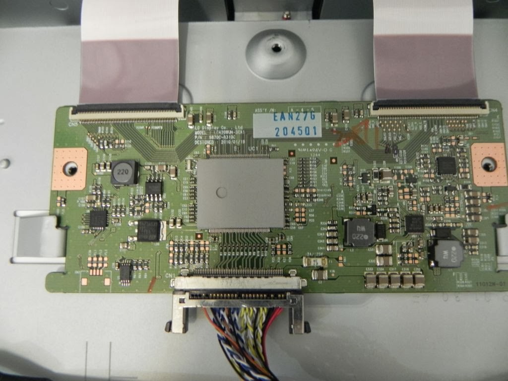
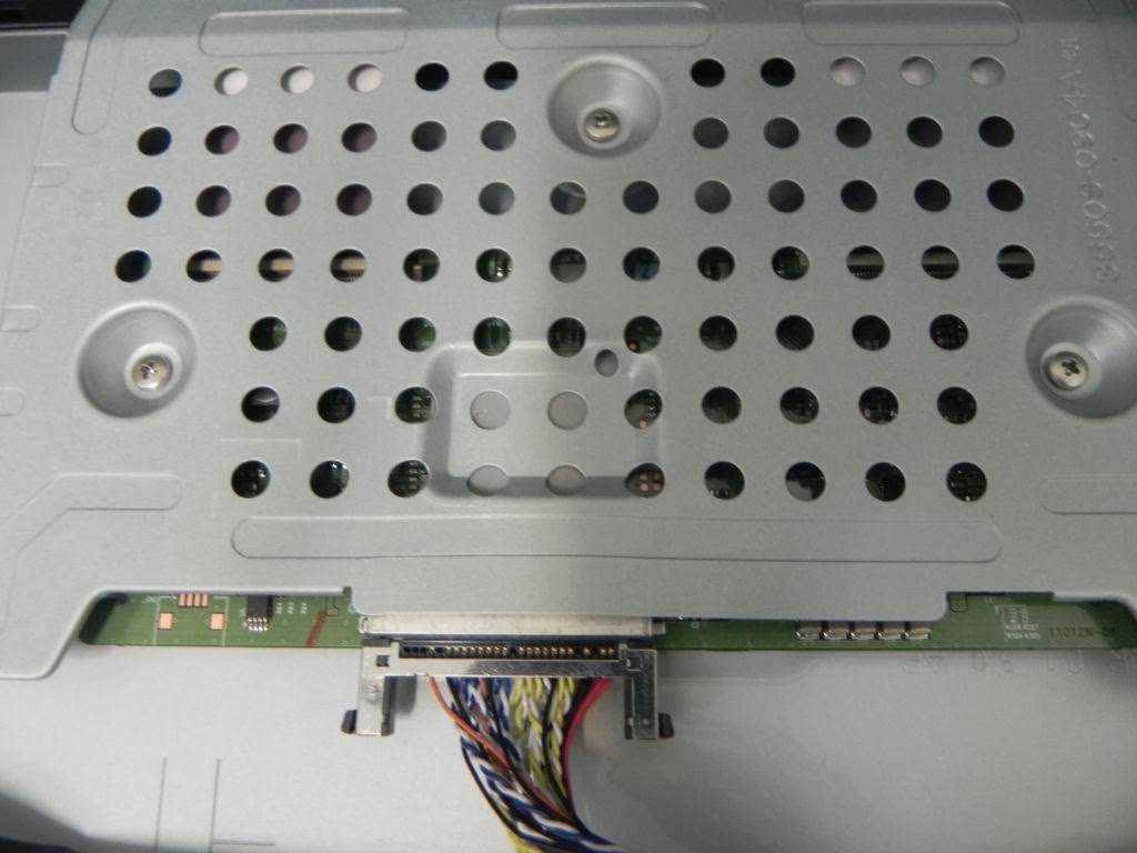
To improve more the cooling on the T-Con LCD panel board we put a SinoGuide TCP400 series thermal pad on the main IC to increase the heat transfer on the metallic shield (this is more thick in diameter and seems to be OK for cooling purposes).

Main Industry Application
Customer Help
Production Line
Technical Product Support
Tel.:+86-755-89375091 Fax.:+86-755-89375092 E-mail: sales@sg-thermal.com
Address: Block A, No 3, Zhonghe Street, Pinghu Town, Longgang District, Shenzhen City, China
copyright@2007-2015@SinoGuide Technology Ltd.